Mesh generation for airfoil simulation
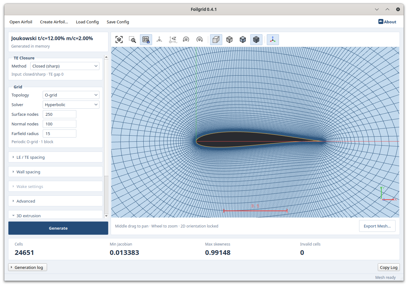
Load airfoil coordinates or create a profile in the application, then set the surface and wall-normal resolution to generate a mesh. Choose hyperbolic marching or elliptic smoothing and adjust the mesh distribution at the leading edge, trailing edge and wake.
Use FoilGrid to prepare airfoil flow simulations and compare mesh topologies and wall spacing. Configure, generate, inspect and export the mesh in a single interface.
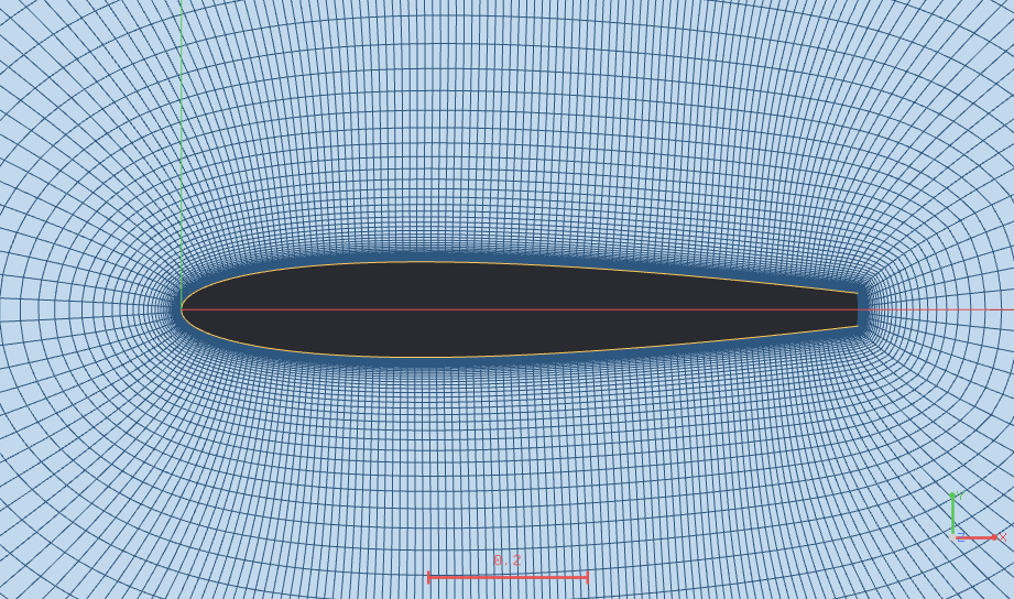
Choose a topology for the geometry
- O-grid
- A single block wraps around the airfoil. Supports rounded or flat closure of an open trailing edge, as well as closed sharp trailing edges.
- C-grid
- A three-block topology that extends mesh lines into the wake from a closed, sharp trailing edge.
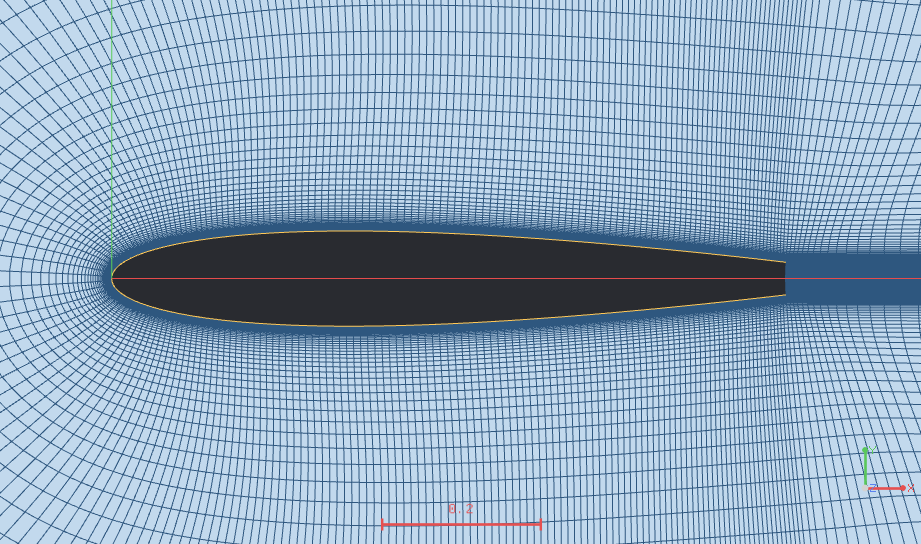
- C-H grid
- A four-block topology that closes an open trailing edge with a flat base and connects it to wake blocks.
O-grid and C-H grid meshes for the same flat trailing-edge profile. Choose how to resolve the trailing edge and wake to suit the geometry and analysis.
From input to export
- 01
Prepare the profile
Open an XFOIL/Selig .dat coordinate file with Open Airfoil, or create a profile with Create Airfoil.
- 02
Configure the mesh
Select the closure and topology for the trailing edge. Set node counts, the farfield, leading- and trailing-edge spacing, and the first-layer height.
- 03
Generate and inspect
Generate the mesh and review its lines and quality metrics. Regenerate after changing settings to update the result.
- 04
Export
After checking quality, use Export Mesh to save a CGNS or VTU file.
Specify the first-layer height directly, or estimate it from y+, Reynolds number and reference chord. The y+-based value is an estimate derived from a flat-plate correlation.
Inspect mesh lines and quality together
- Cells
- Check the final number of cells to be exported.
- Min Jacobian
- The minimum scaled Jacobian indicates cell validity and must be positive.
- Max skewness
- Cell distortion on a scale from 0 to 1; values closer to 0 are ideal.
- Invalid cells
- Cells with non-finite values or a scaled Jacobian at or below zero. This count must be zero to export.
Use mesh lines, zoom and pan to inspect the leading edge, trailing edge, wake and block interfaces. Invalid meshes remain visible for inspection, but export is disabled.
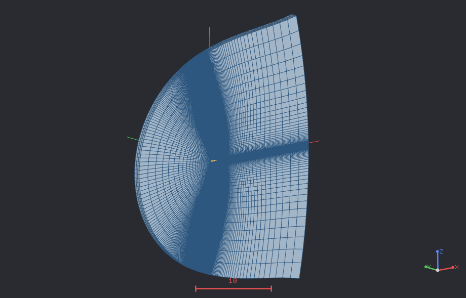
From a 2D section to a 3D mesh
Extrude the generated 2D mesh uniformly over a chosen length and number of divisions. Optionally rotate the output to Z-up. Symmetry boundary markers are assigned to the two end sections.
Input and output
- Input
- XFOIL/Selig labeled-coordinate airfoil .dat files, representing a single continuous airfoil section.
- CGNS
- The default output format. Block-interface nodes are merged into a single unstructured zone, with boundary names and CGNS BC types.
- VTU
- An additional output format for mesh inspection and post-processing.
Unit-chord coordinates are recommended. File input is not automatically normalised or rotated. Check CGNS boundary markers and assign physical boundary conditions in the target solver.