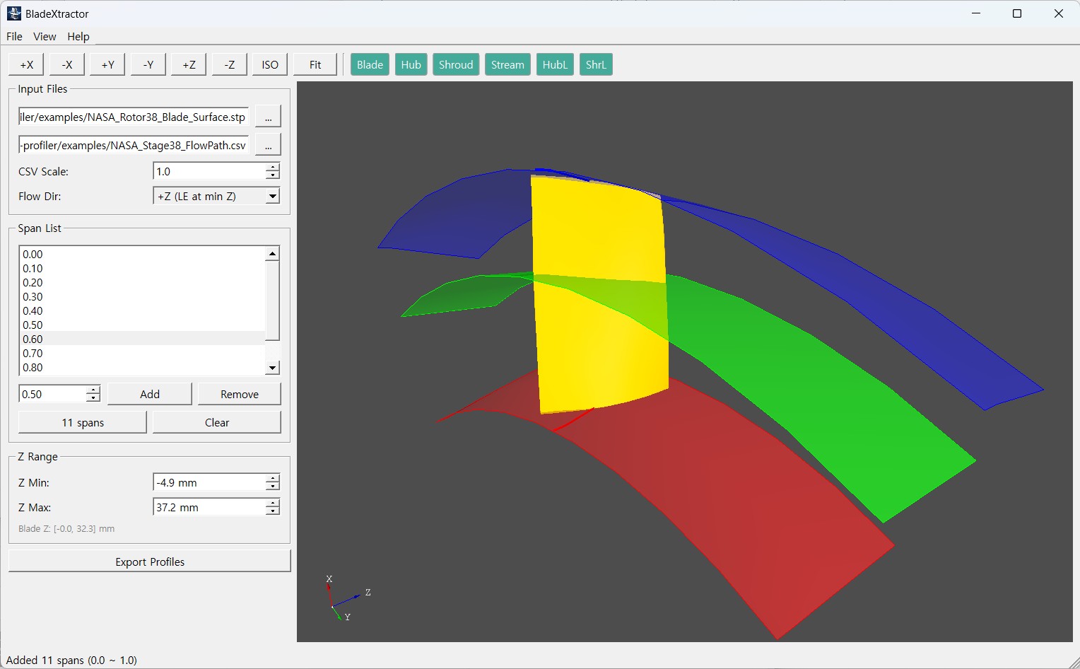
Overview
Working on turbomachinery blades, you often have the 3D CAD geometry but need the exact airfoil point coordinates. BladeXtractor pulls the airfoil section at the span you want straight out of a STEP file and turns it into point data you can use immediately.
Both a GUI and a CLI are provided, so it also runs inside an automated analysis pipeline.
Where it is used
Analyse an existing blade to recover design parameters, or use it as the basis for a new design.
When mesh generation for a CFD study needs exact point coordinates on the blade surface.
Check that the CAD model was built as intended by inspecting the section shape.
Passing geometry into another turbomachinery design or analysis tool.
How it works
- 01 Load the blade STEP file
Read in the existing 3D blade geometry.
- 02 Load the flow path
Define the flow passage on the meridional plane.
- 03 Build the stream surface
Generate the surface of revolution at the requested span.
- 04 Extract the intersection
Compute the intersection curve — the airfoil — between blade and stream surface.
- 05 Write point coordinates
Divide the curve evenly and write out 3D point coordinates (X, Y, Z).
Output format
Written as .curve, the format turbomachinery meshing tools read.
Files written
- Blade_profile.curve
- Blade profiles (all spans)
- Blade_hub.curve
- Hub curve
- Blade_shroud.curve
- Shroud curve
- Blade_debug.stp
- Debug STEP (optional)
System requirements
- Operating system
- Windows 10/11 (64-bit)
- Display
- 1280×800 or larger recommended
- Input files
- STEP (*.stp, *.step), CSV
- Output files
- TEXT (*.txt, *.curve)