1. Overview
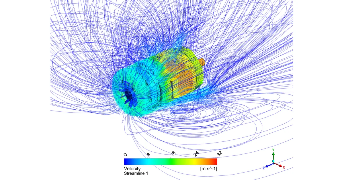
Motor temperature governs insulation life and rating, but it is awkward to reproduce numerically. The heat sources are split between the core and the windings, a flow peculiar to rotation develops in the few millimetres of air gap between rotor and stator, and outside the frame a fan-driven forced convection does the cooling. Leave out any one of the three and accurate temperature prediction becomes difficult.
This article is a case study in which conjugate heat transfer was analysed for a super-premium efficiency induction motor at rated load and compared against measurement. The work was carried out with a commercial CFD code.
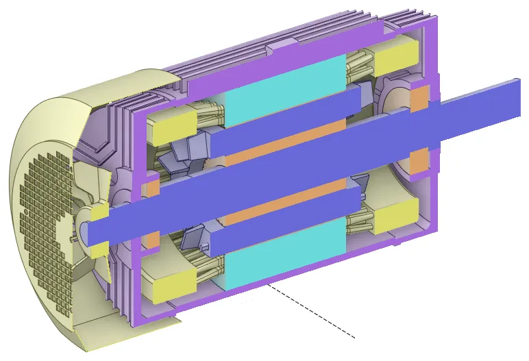
The model includes the frame, stator and rotor cores, windings, rotor cage, shaft, front and rear bearings, fan cover and external fan.
2. What the model has to capture
2.1 Anisotropic conduction in windings and cores
A winding is a composite of copper strands, insulation and potting compound. Individual strands cannot be modelled, so they are replaced by an equivalent thermal conductivity — one whose value differs sharply with direction. Axially the copper is continuous and heat flows readily; radially and tangentially it has to cross insulation and potting compound, and conductivity is far lower. Laminated core steel is anisotropic for the same reason.
Equivalent conductivities were derived from the copper packing factor and the conductivity of each constituent material.
2.2 Air-gap flow — a Taylor number check
Flow in the narrow annulus between rotor and stator is not necessarily a simple laminar shear flow. Above a critical rotational speed, counter-rotating vortex pairs stacked along the axis — Taylor vortices — appear, and they greatly enhance heat transfer across the gap.
Computing the Taylor number from the rotor and stator radii and the rotational speed showed that every condition examined exceeded the critical Taylor number. The air gap of this motor is therefore in the Taylor–Couette regime, and failing to resolve the vortices means underpredicting air-gap heat transfer.
2.3 How much air-gap mesh is enough
Resolving the vortices requires a fine mesh. To find out how fine, we compared the flow structure with the air-gap mesh increased from 155,200 to 512,000, 1,533,000 and 2,380,000 cells.
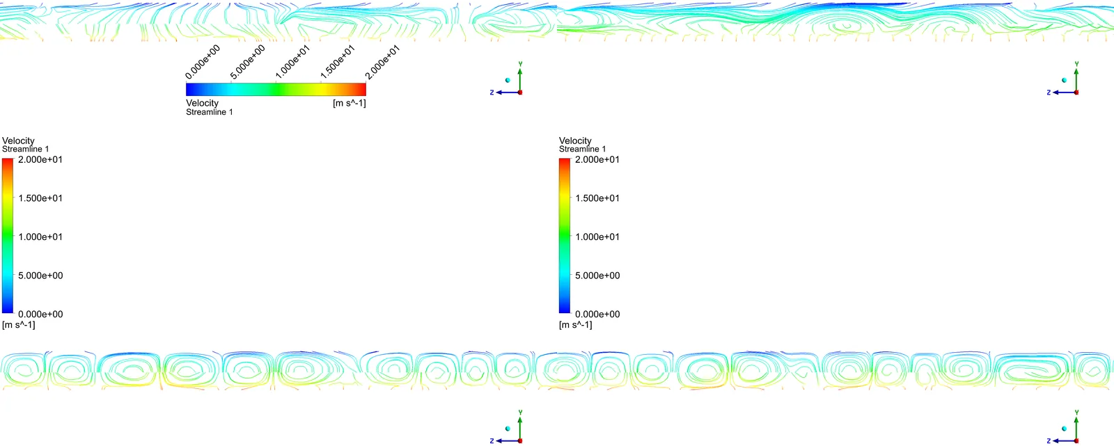
Taylor vortices began to be captured at around one million cells. Below that the vortex structure smears out and the flow looks like a plain shear flow. The air gap is a small region on its own, but skimping on mesh there discards an entire heat transfer path.
3. Analysis setup
Rather than separating the motor interior from the external freestream, the whole thing was solved as a single domain. The fan-driven external flow cools the frame, and that in turn sets the internal temperature.
| Item | Value |
|---|---|
| Interior mesh | 19,700,000 |
| Exterior mesh | 8,250,000 |
| Total mesh | 27,950,000 |
| External domain | 10D upstream, 5D downstream (D = diameter) |
| Time | Steady state |
| Pressure–velocity coupling | Coupled |
| Discretisation | Second-order upwind |
| Turbulence model | SST k-ω |
| Rotation model | Moving reference frame |
| Rotational speed | 1,783 rpm |
Heat generation was assigned separately by region — stator core, rotor core, windings and cage.
4. Results
4.1 Temperature distribution against measurement
| Region | Measured [°C] | CFD [°C] | Difference |
|---|---|---|---|
| Winding | 54.4 | 59.4 | 5.0 |
| Rotor core | — | 69.0 | — |
| Rotor cage | — | 68.0 | — |
| Front bearing | — | 67.8 | — |
| Shaft | — | 65.4 | — |
| Rear bearing | — | 65.0 | — |
| Stator core | — | 56.6 | — |
| Frame | — | 49.5 | — |
| Internal air | — | 43.4 | — |
At the winding, the one location with measured data, the agreement was reasonably close at 5.0°C. No measurements were available for the remaining regions, so only computed values are given.
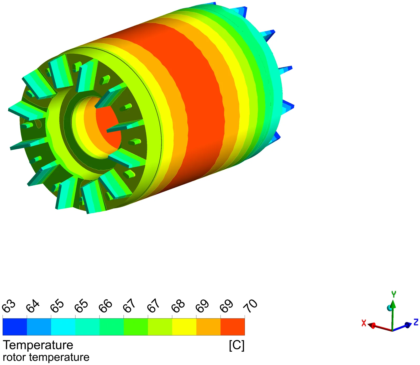
The hottest regions are the rotor core (69.0°C) and the cage (68.0°C); the coolest are the frame (49.5°C) and the internal air (43.4°C). The heat is concentrated in the rotor, and the path by which it leaves through the air gap and the shaft shows up directly in the field.
4.2 External fan flow — the cooling is not uniform
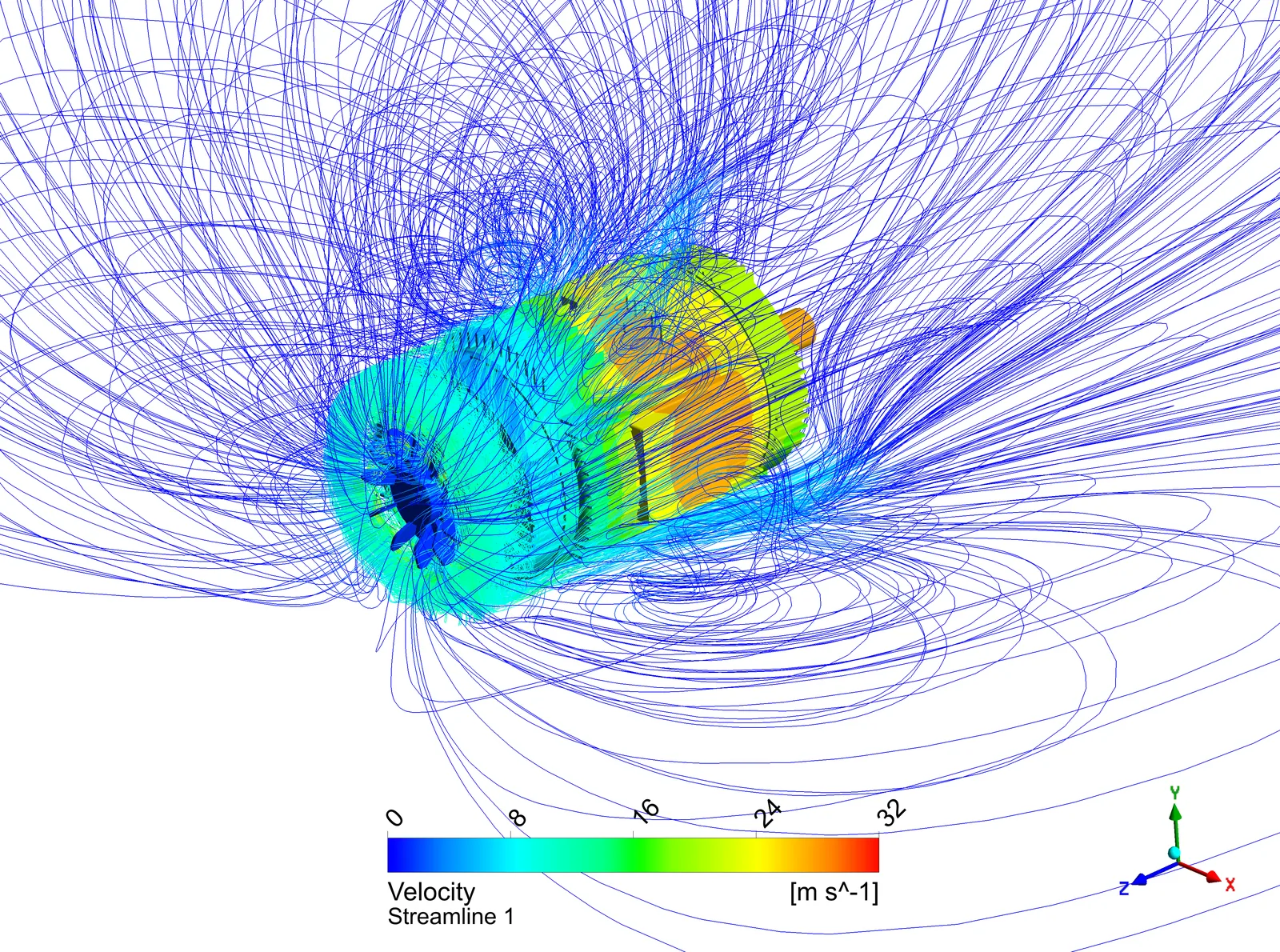
Two biases appear in the temperature field.
- The lower half runs hotter. The ground blocks the fan flow and weakens cooling underneath.
- It gets hotter towards the front. Flow leaving the fan separates part-way along the frame and never reaches the front.
Air leaving the fan cover was also found to recirculate back into the fan rather than travelling far. This is not the kind of problem that a larger fan fixes on its own.
4.3 Internal flow stagnation
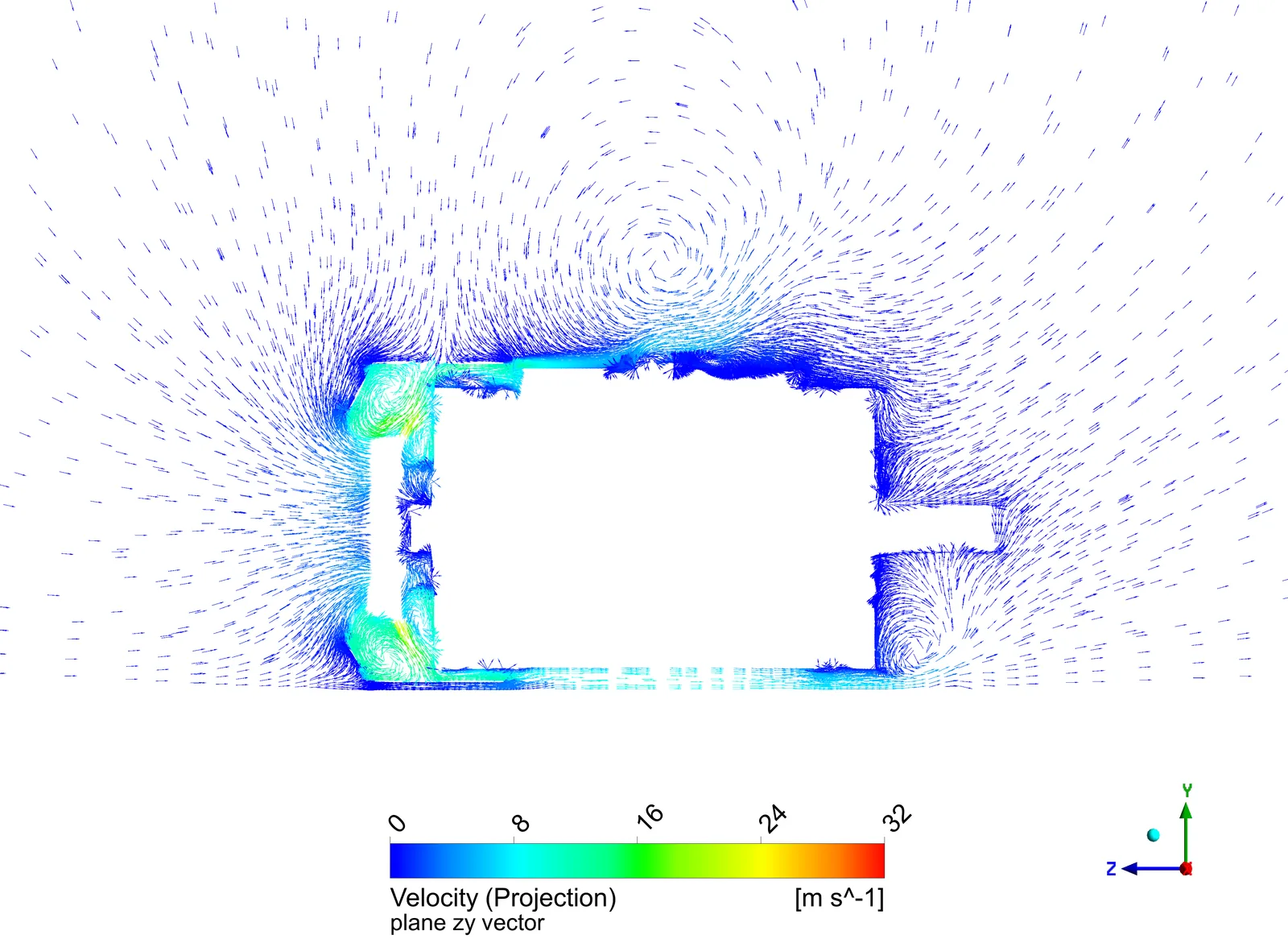
Internally the local temperature spread was fairly large, and stagnant flow appears to be the cause. Circulation forms around the coil ends, but in the space between them the air barely moves.
5. Conclusions
Thermal behaviour of an induction motor at rated load was analysed with CFD and compared against measurement. The difference at the winding was about 5°C, a reasonably close agreement.
The factors this case identified as ones not to omit in motor thermal analysis are:
- Enhanced heat transfer by Taylor vortices in the air gap — check first whether the critical Taylor number is exceeded, and if it is, mesh finely enough to resolve the vortices
- Anisotropic conduction in cores and windings — equivalent conductivity differs sharply with direction
- Reduced cooling from the external fan flow pattern — ground effect, separation part-way along the frame, recirculation at the fan cover
- Local temperature spread from internal flow stagnation
The first two belong to the modelling stage, the last two to design improvement.